Commons is a freely licensed media file repository. You can help.

|
File:CmosXORGate.svg is a vector version of this file. It should be used in place of this PNG file when not inferior.
File:CmosXORGate.png → File:CmosXORGate.svg
For more information, see Help:SVG. |
 |
Summary
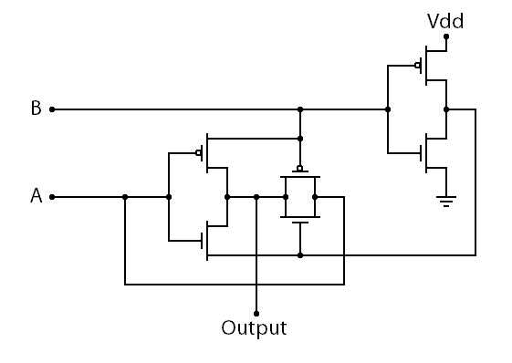
| Description | A picture of transmission gate logic implementation of an XOR gate | ||
| Date | 07Jan10 | ||
| Source | www.falstad.com/circuit | ||
| Author | Paul Falstad | ||
| Permission (Reusing this file) |
This screenshot either does not contain copyright-eligible parts or visuals of copyrighted software, or the author has released it under a free license (which should be indicated beneath this notice), and as such follows the licensing guidelines for screenshots of Wikimedia Commons. You may use it freely according to its particular license. Free software license:
Note: if the screenshot shows any work that is not a direct result of the program code itself, such as a text or graphics that are not part of the program, the license for that work must be indicated separately. |

Licensing
| This work is ineligible for copyright and therefore in the public domain because it consists entirely of information that is common property and contains no original authorship. |
File history
Click on a date/time to view the file as it appeared at that time.
| Date/Time | Thumbnail | Dimensions | User | Comment | |
|---|---|---|---|---|---|
| current | 22:41, 9 November 2022 | | 561 × 398 (5 KB) | Crystallizedcarbon | Changed Vcc to Vdd since transistors in inverter are now FETs and improved text |
| 11:21, 9 November 2022 |  | 561 × 398 (3 KB) | Crystallizedcarbon | Changed order of the inputs to match that of a previous circuit in the article | |
| 18:40, 5 February 2010 |  | 561 × 398 (8 KB) | Wikidood123456789 | Symbol change | |
| 09:44, 7 January 2010 |  | 604 × 355 (8 KB) | Wikidood123456789 | {{Information |Description=A picture of a cmos XOR gate |Source=www.falstad.com/circuit |Date=07Jan10 |Author=Paul Falstad |Permission={{free screenshot|license={{GPL}}}} |other_versions= }} Category:Electronics |
File usage
The following 2 pages use this file:
Global file usage
The following other wikis use this file: